

Sanitary Material Handling and Hygienic Equipment
How to Choose the Right Optical Attenuator?
Choosing the right Optical Attenuator is not simply a matter of selecting a lower power level. It is a practical engineering decision involving wavelength, connector type, attenuation range, accuracy, and operating conditions. A device that works well at 1550 nm may perform differently at 850 nm. Small details matter. Even a polished connector can introduce unexpected loss.
Professor Alan E. Willner, a recognized optical communications expert, has said, “The design of optical networks is a balance between performance, flexibility, and cost.” This principle applies directly to attenuator selection. Fixed attenuators may offer stable, economical control in established links. Variable attenuators provide flexibility during testing, calibration, and network adjustment. However, flexibility can bring greater complexity and more opportunities for measurement error.
The best choice depends on the actual system, not a product label. Engineers should check insertion loss, return loss, power-handling capability, polarization sensitivity, and environmental stability. They should also confirm whether the attenuator is compatible with single-mode or multimode fiber. Laboratory conditions can hide problems. Outdoor cabinets, repeated reconnection, dust, vibration, and temperature changes often reveal them.
Some decisions remain imperfect. Datasheet values may not match field performance exactly. Measurement equipment can also influence the result. A careful selection process therefore includes testing with the intended transmitter, receiver, connectors, and wavelength. This guide explains how to compare Optical Attenuator types, avoid common selection mistakes, and build a more dependable link without paying for features the system does not need.
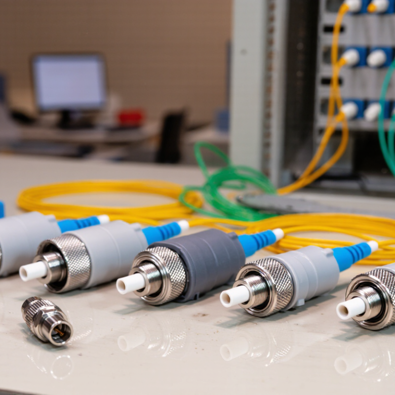
What Is an Optical Attenuator and Why Is It Used?
An optical attenuator is a passive device that reduces optical power in a fiber link. It adds controlled loss, measured in decibels (dB). A 3 dB attenuator roughly halves the optical power reaching the receiver. This simple function prevents overload when a transmitter is stronger than the receiving port can safely accept. Attenuators may be fixed or adjustable. Fixed models provide stable loss. Variable models support testing and calibration.
Why use one? Fiber systems often connect components with different power budgets. A short cable can deliver excessive light, especially after a powerful transmitter is installed. Excess power may cause receiver saturation, unstable readings, or misleading fault reports. Engineers also use attenuators to simulate long links and verify receiver sensitivity. During commissioning, measure power before and after insertion with a calibrated optical power meter. Do not rely on the printed value alone. Connector cleanliness and wavelength can change the actual result.
Choosing the right attenuator requires matching fiber type, connector style, operating wavelength, and required loss. Its power rating should exceed the expected input, with sensible margin. An inline device is convenient, but every extra connection introduces reflection and handling risk. The first estimate is not always correct. A measured link budget is safer than guesswork. Recheck the signal after temperature changes or connector work. Even a small mismatch can become visible at high data rates.
| Selection Dimension | Typical Data or Range | Why It Matters | Recommended Selection Consideration |
|---|---|---|---|
| Optical Attenuator Fundamentals | |||
| Primary Function | Reduces optical power by a specified amount, measured in decibels (dB). | Prevents excessive input power from causing receiver overload, measurement errors, or nonlinear effects. | Choose an attenuation value that keeps the received power within the equipment's specified operating range. |
| Attenuation Principle | Absorption, reflection, scattering, controlled air gap, or a combination of optical and mechanical methods. | The principle affects insertion loss, return loss, wavelength behavior, and power-handling capability. | For precision links, prioritize stable attenuation and low reflection. For simple testing, a fixed attenuator may be sufficient. |
| Attenuation Unit | Decibel (dB); optical power transmission is commonly expressed as a percentage or ratio. | A logarithmic scale makes it easier to specify large power reductions. | Confirm whether the stated value is nominal attenuation or measured attenuation at a specific wavelength. |
| Typical Applications | Receiver overload protection, optical power equalization, network testing, link-margin verification, and instrument calibration. | Different applications require different levels of adjustment, stability, and repeatability. | Define the application before selecting the attenuator type and attenuation range. |
| Comparison of Common Optical Attenuator Types | |||
| Fixed Attenuator | Common nominal values include 1, 3, 5, 10, 15, and 20 dB. | Provides a constant reduction in optical power with a simple and compact structure. | Best for permanent installation when the required attenuation is known and does not need adjustment. |
| Variable Optical Attenuator | Typical adjustable ranges include 0–10 dB, 0–20 dB, or wider ranges depending on the design. | Allows optical power to be tuned during testing, commissioning, or changing network conditions. | Choose a model with sufficient adjustment range, fine resolution, low drift, and repeatable settings. |
| In-Line Attenuator | Installed directly in the optical path using mating connectors or a short optical assembly. | Offers convenient installation without requiring a separate optical module or equipment rack. | Match the connector interface, fiber type, polarity, and environmental rating to the link. |
| Connector-Style Attenuator | Usually available as a connector-mounted component with a predefined attenuation value. | Provides a quick plug-in solution for reducing power at a specific connection point. | Verify connector compatibility and ensure that repeated mating will not compromise cleanliness or return loss. |
| Bulkhead Attenuator | Mounted through a panel or adapter plate and connected from both sides. | Supports organized, semi-permanent installation in distribution panels and test fixtures. | Consider panel dimensions, connector orientation, mounting method, and cable-management requirements. |
| Motorized or Programmable Attenuator | Electronically controlled attenuation with software or automated test-system integration. | Supports repeatable remote adjustment and automated measurement sequences. | Check control interface, positioning repeatability, switching speed, power supply, and automation compatibility. |
| Key Technical Parameters | |||
| Attenuation Range | Fixed values or an adjustable range stated in dB. | Determines whether the component can achieve the required optical power level. | Select a range that covers the maximum expected attenuation while retaining useful adjustment resolution. |
| Attenuation Accuracy | Specified as the difference between the actual and nominal attenuation, commonly expressed in dB. | Influences power-budget calculations and the accuracy of receiver-sensitivity tests. | Use tighter accuracy for laboratory measurements, calibration, and high-precision link testing. |
| Operating Wavelength | Common fiber-optic windows include approximately 850 nm, 1310 nm, and 1550 nm. | Attenuation can vary with wavelength, especially in designs that are not broadband. | Choose a wavelength-compatible attenuator and review its performance across the complete operating band. |
| Wavelength Bandwidth | May be single-window, dual-window, or broadband across multiple telecom or datacom bands. | A wider bandwidth is important for systems using wavelength-division multiplexing or multiple transceiver types. | Confirm the attenuation flatness across all wavelengths used by the system. |
| Insertion Loss | Additional loss introduced by the component beyond its intended attenuation. | Excess insertion loss reduces the available optical power budget. | Compare the specified insertion loss with the link budget, especially for short-reach systems with limited margin. |
| Return Loss | Reflection performance expressed in decibels; higher return-loss values generally indicate lower reflected power. | Reflections can affect lasers, coherent systems, interferometric measurements, and sensitive receivers. | Choose a higher-return-loss design when the transmitter or measurement system is sensitive to optical reflections. |
| Fiber Type | Single-mode fiber is commonly used for long-distance and wavelength-specific links; multimode fiber is commonly used for short-reach datacom links. | Mode mismatch can create coupling loss and measurement uncertainty. | Match the attenuator to the fiber core, mode-field characteristics, and system transmission technology. |
| Maximum Optical Input Power | Specified by the manufacturer for continuous or peak optical power conditions. | Exceeding the rating may cause heating, drift, permanent damage, or unreliable attenuation. | Choose a power rating above the highest expected input level and consider the operating temperature. |
| Polarization Dependence | Variation in attenuation caused by changes in the polarization state of the input light. | Low polarization dependence is important for polarization-sensitive and precision measurement systems. | Review polarization-dependent loss when testing coherent, polarization-maintaining, or high-accuracy systems. |
| Temperature Stability | Change in attenuation or other optical parameters over the specified operating temperature range. | Temperature changes can alter component alignment and attenuation accuracy. | Select a thermally stable design for outdoor cabinets, industrial environments, and long-duration measurements. |
| Connector Interface | Common interfaces include LC, SC, ST, FC, and connectorless fiber configurations. | Mechanical incompatibility prevents installation and may increase coupling loss or reflection. | Match connector type, polish style, key orientation, and adapter requirements before ordering. |
| Environmental Protection | May include indoor, outdoor, dust-resistant, moisture-resistant, or ruggedized construction. | Contamination, vibration, humidity, and temperature cycling can affect optical performance. | Choose an environmental rating suitable for the actual installation location rather than the laboratory specification alone. |
| Practical Selection Guide | |||
| Known and Constant Power Reduction | Use a fixed attenuator with the required nominal dB value. | Minimizes complexity and provides a stable, economical solution. | Verify attenuation accuracy, wavelength, connector type, and power rating. |
| Frequent Testing or Calibration | Use a variable or programmable attenuator with a suitable adjustment range. | Allows multiple test conditions to be created without changing components. | Prioritize repeatability, resolution, calibration capability, and control integration. |
| High-Reflection-Sensitivity System | Use an attenuator with strong return-loss performance and low reflected power. | Reduces interference and instability caused by back reflections. | Review return loss, polarization dependence, and connector end-face quality. |
| Multiple Wavelengths | Use a broadband or wavelength-qualified attenuator. | Helps maintain predictable attenuation across the entire operating band. | Check wavelength-dependent attenuation and flatness rather than relying on a single test wavelength. |
| High Optical Power | Use a high-power-rated attenuator designed for the expected continuous-wave or peak input. | Reduces the risk of thermal damage and attenuation drift. | Include operating temperature, duty cycle, beam conditions, and safety limits in the selection process. |
| Limited Link Budget | Use the lowest attenuation value that achieves receiver protection or test objectives. | Every additional dB reduces the available power margin. | Calculate transmitter output, connector loss, splice loss, fiber loss, attenuator loss, and receiver sensitivity together. |
| Final Verification Before Installation | Confirm attenuation, wavelength, connector interface, fiber type, power handling, return loss, and environmental requirements. | A technically suitable attenuation value can still be unusable if the mechanical or environmental specifications do not match. | Always compare the component specification with the complete optical link budget and the equipment manufacturer's allowable input-power range. |